Category Menu

Solutions To Integrate Different Industries And Increasing Speed And Efficiency

Wiedemanntech are specialists in the development and manufacturing of sensors with the capability of data synchronization to PLC & HMI for monitoring and accurate measuring fill levels. Wiedemanntech provides the most innovative technology in fuel management systems and creative solutions which allow our customers from the oil, chemical and pharmaceutical industries to put trust in our products which have the highest level of accuracy and efficiency along with reducing costs and intermediary circuits.

What is automatic tank gauging system?

The petrol station automatic tank gauging system is used to replace the manual measurement of oil level, water level, and oil temperature, and has become the main method of petrol station purchase, sales and inventory management. The automatic tank gauging system is an intelligent system that meets the needs of modern petrol station management. It is composed of magnetostrictive leve probe and console, which can reflect the fuel level, water level, temperature and purchase, sales and inventory information of the oil tank.​

How do Magnetostrictive sensors work?

In magnetostrictive sensors, the wire, or bar, is referred to as a waveguide. It is typically made from an iron alloy and is mounted to a stationary part of the machine. The magnetic field is provided by a magnet, referred to as a position magnet, which is attached to the moving part being measured. Short pulses of current (1-3 μs) are applied to a conductor attached to the waveguide.

Magnetostrictive sensors
The basic components of a magnetostrictive sensor include the waveguide, the position magnet, and a strain pulse converter.
As the Wiedemann effect states, torsional strain (twist) is induced in the waveguide, due to the interaction of the magnetic field caused by the current and the magnetic field caused by the position magnet. Because the current is applied as a pulse (referred to as an interrogation pulse), the twist travels down the wire as an ultrasonic wave, moving at approximately 2850 m/s. This twist, or mechanical pulse, is detected by a signal converter (also referred to as a strain pulse converter), which relies on the Villari effect to create a voltage pulse indicating receipt of themechanical strain wave.

When a current pulse is applied, the magnetic fields created by the current and the position magnet interact and cause torsional deflection in the waveguide. When the current is turned off, the strain relaxes, and a mechanical wave begins to propagate. The wave propagates in both directions. In one direction, it is detected by the signal (pulse) converter. In the other direction, it is eliminated by a damping device to avoid interference.

The time between the initial current pulse and the detection of the mechanical pulse indicates the location of the position magnet, and therefore, the position of the moving part being measured. The interrogation rate, or update rate, can range from one time per second to over 4000 times per second, with the maximum update rate determined by the length of the waveguide.

Magnetostrictive sensors provide absolute position information and, unlike incremental encoders, do not need to be re-homed when there is a loss of power. They can also use multiple position magnets with one waveguide, making them well-suited for applications that require position information for multiple components along the same axis, such as the knives on a slitting machine.

In addition to being non-contact, magnetostrictive designs enclose the waveguide in an extruded aluminum housing or stainless steel tube, so they are virtually impervious to contamination. They can also operate when there is a barrier between the position magnet and the waveguide — as long as the barrier is non-magnetic, such as ceramic, plastic, aluminum, or stainless steel.

The policy of Wiedemanntech company is that:

Always, we try to use services and products of other companies and external contractors, because it can reduce the company's current costs. In addition, it can have a positive impact on the economic activity of other companies. As a result, we have been able to focus on improving the designs of our products.

What is HMI & PLC?

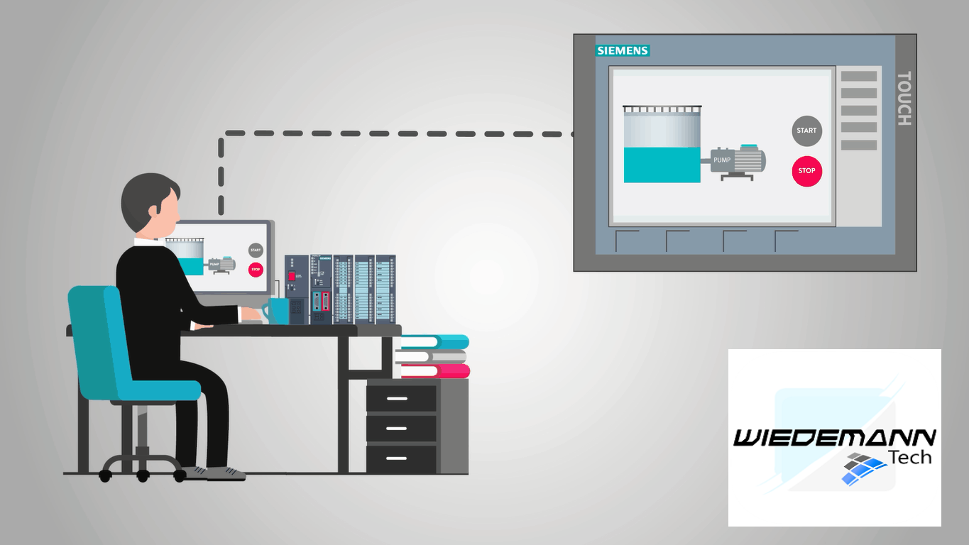
Let’s talk about industrial HMIs now. It would be hard to have a good automated process in industry without an HMI. Many times an HMI will be in the form of a screen, kind of like a computer screen, and more times than not, they are touch screen.

An operator or maintenance personnel can operate and monitor the machine from the HMI.

They may include information like temperature, pressure, process steps, and material counts. They can also show very precise levels in tanks and exact positioning of machines.

Where machine information used to be viewed on multiple indicators can now be viewed on one screen. The possibilities are only limited to the software and hardware used.

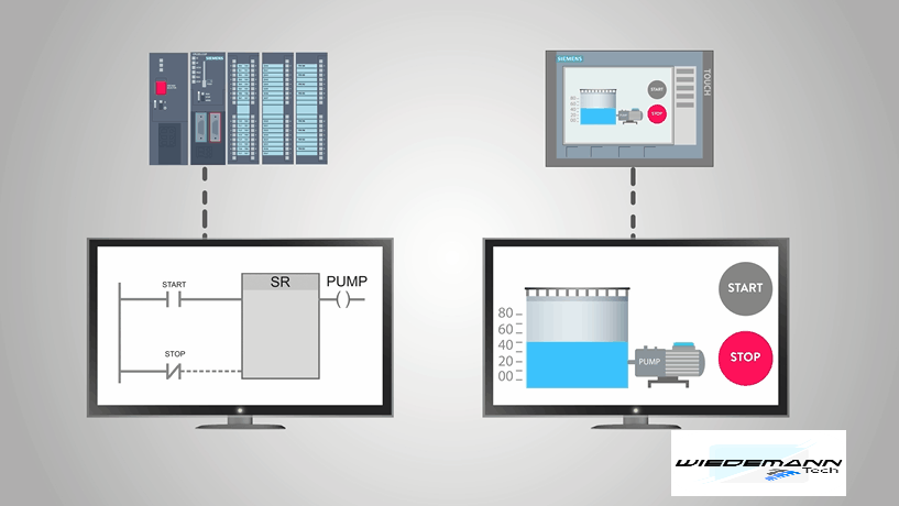
For maintenance personnel, many HMIs can also connect to PLC logic and display it on the screen for troubleshooting purposes. This can save valuable time compared to connecting a computer or laptop every time.

Another benefit of having a modern HMI is the fact that plants and other industrial sites can monitor and control multiple machines or other equipment. A small manufacturing facility could even monitor the entire plant on one centrally located HMI.

Water and wastewater facilities have utilized this for years by coupling an HMI with a PLC. They are able to monitor remote locations, like water pumps, as well as equipment inside the plant.

You probably get the idea now that an HMI is the operating panel and monitoring screen. But how does the HMI actually connect to the machine to be able to control and monitor it? Let’s take a look.

First, HMIs use special software so engineers can program them correctly. Different brands of panels use different software accordingly.

The software allows the engineer to design what the operator will actually see on the screen, what they can monitor on the screen, what “buttons” can be pushed, and how the operator can manipulate the machine.

For example, an HMI may have a large tank displayed on the screen with the level of a liquid displayed. Next to the tank is a pump to lower the liquid level.

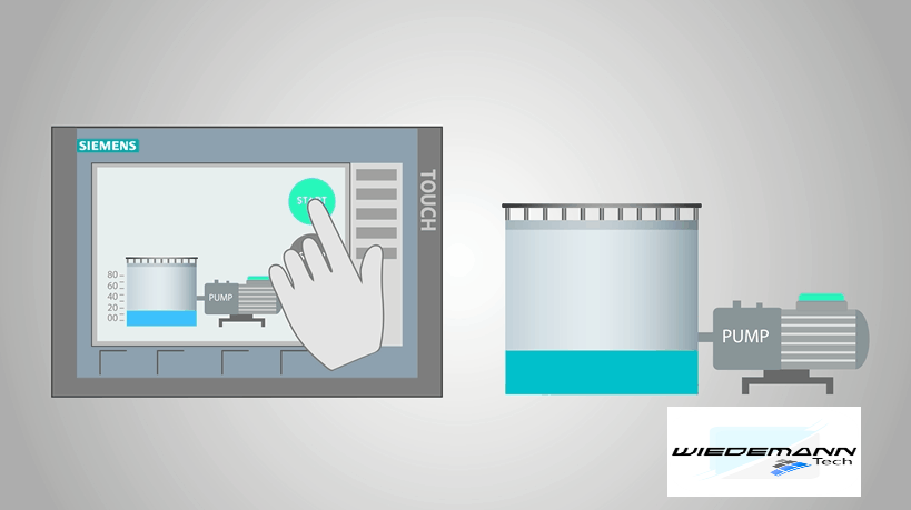
An HMI can also have the start and stop button displayed and usable on the screen next to the pump.

This display would be able to actually turn the pump on and off.

But, it is not as easy as just placing a button on the screen or a tank with a level on the screen.

The person doing the HMI programming has to program each indicator and button to a specific input or output address of a PLC.

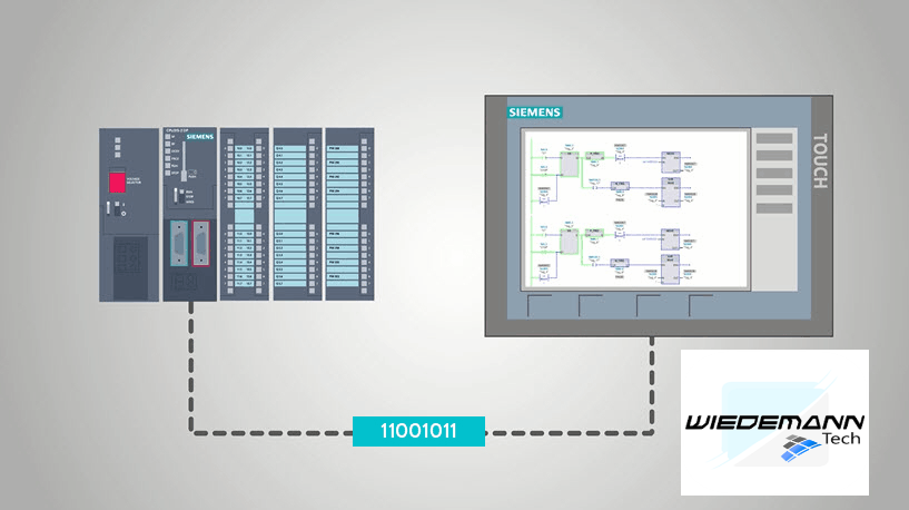
This brings up another point, the HMI and PLC need to be compatible. This means they need to be able to “talk” to each other. They do this on what is called a Protocol. Different companies use different protocols.

Common protocols are Modbus, Ethernet/IP, and Profibus. These are all just industrial networks, kind of like the network you may have in your home with multiple computers, tv’s or other devices connected to each other.

Protocol information is easily found on each manufacturer’s website.

Once the PLC and the HMI are “talking” then whatever is programmed into the HMI can be used to monitor and control PLC functions.

Let’s review, today you have learned some of the basics of an HMI or Human Machine Interface. These are the monitors and controls of a machine that allows the operator to run a machine or monitor a machine.

Engineers can program an HMI to perform almost any function that can be controlled or information that can be monitored by a PLC. HMIs and PLCs work together to monitor and control the machine. This means they have to be compatible and they also have to speak the same language so to speak.

This comes in the form of a Protocol which is just an industrial network.